Manufacturing
How to cut a Gear
CNC Machining or Laser Cutting
Designing Gear Trains
For the purposes of this project, we will be using a cycloid
gear tooth profile,
instead of the standard involute profile used in industry. Cycloid gers are just easier to cut, and have been used
in clocks, some of the oldest gear trains still running!
Since you have yet to take learn about gear trains in your course
work,
a few definitions are in order.
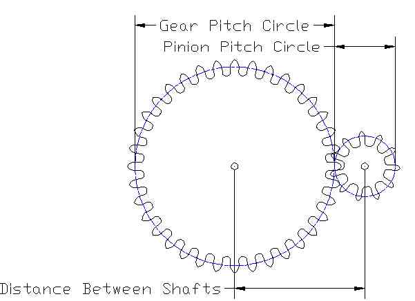
The big gear is called a gear, the small gear is called a pinion.
Two gears should be sparated my the half of the sum of the two pitch
circle diameters.
We have found that gears of a diametral pitch of 10 is about the
minimum
size possible with the MDF board.
(diametral pitch is the number of teeth on a gear per inch of its
diameter)
All gears drawn to the same diametral pitch will mesh properly with
each other.
This makes calculations easy, if you want a 36 tooth gear, its pitch
circle diameter is 36/10=3.6".
Thus for the above figure, with a 36 tooth gear and a 11 tooth pinion,
they should be separated by:
Gear pitch dia. 36 tooth /10 diametral pitch = 3.6"
Pinion pitch dia. 11 tooth /10 diametral pitch = 1.1"
Shaft to shaft distance = (3.6"/2) + (1.1"/2) = 2.35"
Gear Ratios
For the above gear train, each revolution of the 11 tooth pinion,
will,
of course, move the 36 tooth gear through 11 teeth.
OR
11/36 = .31 of a revolution
OR
.31 x 360 degrees = 110 degrees
Drawing Gears Simplified
For this simplified cycloid gear profile;
the distance from the pitch circle to the top of the gear tooth is
the addendum,
the distance from the pitch circle to the bottom of the gear tooth
is the dedendum.
Begin by drawing the pitch circle.
(number of teeth/10 = circle diameter)
Now draw the the top tooth.
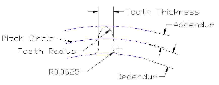
Notice that the center of the tooth radius is at the intersection
between
the tooth thickness and the pitch circle.
For simplicity, a radius of 0.0625" is used at the root of the tooth.
If you are drawing in AutoCAD, draw one tooth at the 12 o'clock
position
as shown.
Make sure that all the lines end and start at the same point.
Use the "PEDIT" command to transform all the individual lines into
one long "Polyline".
Then, use the "ARRAY" command, in Polar mode to copy your teeth around
the gear.
Finally, join all the gear teeth together with the "PEDIT" command.
The tables below list the appropriate values for gears and pinions
of
10 diametral pitch.
FOR GEARS